Wednesday, April 1, 2017
Fixing a Textronix FG502
At some point in the last few years my trusty Textronix FG502 failed. The output would not go negative, and seemed stuck about a diode drop above ground. But the beautiful thing about vintage Tek gear is that they were designed for repair: the manuals have complete schematics and even the construction makes servicing simple. Look at the picture below: the mainframe cover comes off with just 4 screws and the module cover just pops off, allowing you easy access to the PCB. I have an Ikea-effect investment in this particular boat anchor as I pulled it out of a dumpster some years ago and restored it to health. (It worked perfectly, but someone must have thought it was dead because the incandescent power lamp was burned out, easily fixed with a new 12V grain-of-wheat bulb.)

Here are two manuals I found:
My first suspicion was the output stage, as I have regularly abused it, even directly driving voice coils with it once. But a quick measurement of the power rails showed the negative rail was not in fact -20V DC like it should have been, but stuck a diode-drop above ground. OK! Likely one of the ancient electrolytic caps of which there are several and they are notorious for drying out and failing with age. A quick check of those showed nothing suspicious, none were shorted and they all seemed to charge up when measured with a ohmmeter. (Drat, beacuse that would have been an easy fix!) I then I spent some time on a close visual inspection, but everything looked fine, no suspciously toasted resistors or bad solder joints. Next I measured all the diodes, they all rung out fine, and then measured everything with the power on. Nothing suspicious: the unregulated negative supply across C680 was a good -27V indicating the problem was in the negative regulation circuit.
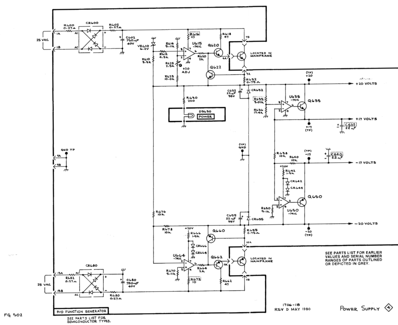
OK this was progress: we've narrowed it down to just a few components. On to the schematic! There was one enable transistor in the mainframe (for sequenced powerup?) so I checked the connectivity of the edge connector which seemed fine. The negative regulation is a transistor-boosted op-amp U664 which just inverts the +20V rail. The +20V rail uses a similar op-amp circuit U615 but amplifies a zener reference VR610 to +20V.
So what to do? Something was wrong -- I checked the resistor values which looked reasonable (as well as I could measure them in-circuit), so it was more likely the boost transistors or the op-amp. Hope it's not a transistor as finding a spare of this vintage is not going to be fun. But both positive and negative op-amps were socketed so an easy thing to try was to switch them (the 8-pin DIPS next to the big electrolytics in the image below).

I know something was wrong the minute I turned on the power because the incandescent indicator light was noticeably brighter. Whoops! I measured +27V at the +20V rail and -27V at the -20V rail. I quickly turned off the power before something fried. (Hey, it's all analog, should have some headroom, right?) But there was our culprit: one op-amp was bad -- when the good one was in the negative regulator, it mirrored the positive voltage as desired, too bad the bad one I swapped in left the positive rail unregulated!
So all we needed to do was replace the op-amp. No problem, right? It's 8-pin dip, standard op-amp pinout. But hey, what's that part number? Oh, right, it's some Tektronix house part #156-0067-06. Where will I find one of those? But in the later manual, it's listed as a CA741CJG what ever that is. Looked close enough to a LM741 for me, so I popped two of them in, and voilà: solid +20 and -20 volts on the power rails just like they should be, huzzah, and a quick check with the scope shows the function generator generates functions again. Fixed!

But wait, what's that smell? It's something burning -- not a good sign! Following my nose, it's C640, a 22uF cap in the power supply on the -17V rail. Looks like one of those dipped tantalum jobs that are really not happy with reverse voltages, which likely happened when the negative rail went out. In any event, I had a perfect replacement in my parts box: swapped it in, and everything seems happy!

So these boat anchors are eminently fixable, and you can learn some analog things on the way. I remember current-boosting an op-amp with a transistor is covered in Art of Electronics, but there's still some mojo I don't understand: why do the voltage regulation circuits need a different kind of op-amp? And why does the virtual ground on U664 need a 5.1K resistor to actual ground?