Wednesday, June 19, 2013
Dimming an LED lamp with an Arduino
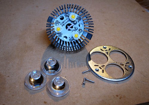
So I've been happy with these inexpensive 12V LED bulbs from Cree available at amazon.com. At 9 watts, they are as bright as a 35 watt halogen, cheap, and relatively good color. Also they are easy to take apart and hack!
Here's another easy hack that lets you dim them smoothly and fully. Though you can dim the 120V versions using a dimmer, it's not very linear, and hard to control remotely. Here's an easy way using PWM from an Arduino or any similar microcontroller.

The trick is to use a FET to bypass the driver current around the LEDs. If you are used to voltage sources like batteries or DC power supplies, this sounds wrong: won't the FET "short out" the driver? Well, yes it does; the trick here is that power LEDs are driven by a current source, which is completely fine to short.
So just solder the bypass wires to the LED driver terminals marked "+" (pink wire) and "-" (white wire) in the image below (click for high resolution). Since it's on a heatsink you might need to increase the heat on your soldering iron.

The voltage sources you are used to want to deliver a constant voltage regardless of the load. Thus they "prefer" an open circuit (so they don't have to do any work) and they "hate" short circuits because they would have to supply infinite current to maintain a constant voltage across a short. Boom!
A current source, on the other hand, is the dual of a voltage source: it wants to deliver a constant current regardless of the load. So it is happiest driving a short circuit, because it needs no voltage to deliver its rated current. But it "hates" open circuits, because it would need to supply infinite voltage to generate a current across an open circuit. Again, boom!
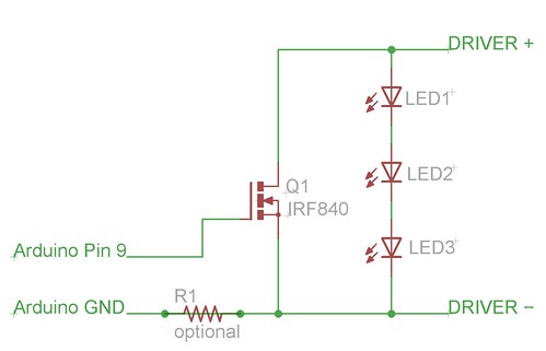
So here's the circuit, it's dead simple:

A logic high from the arduino on pin 9 turns on the FET, and shunts the current through the FET rather than the LEDs (because the voltage drop across the low on-resistance of the FET is much less than Vf of the diodes). This does not bother the current source driving the LEDs: all it wants to do is deliver its set current (in this case, about an amp) and it doesn't care whether it's through the LEDs or the FET. I'm using an IRF840 (pdf datasheet) FET because I had one lying around from repairing some motor controllers, you can use any FET with a logic-level threshold like a IRF512.
I did this modification with a 12V bulb, but it should work with a 120V bulb if the LED driver is floating. To find out, you should check the voltage between the driver negative and the arduino GND before connecting them: don't connect them if it's at all large, and you might want to add the optional resistor R1 with a value of a few K as isolation. Of course you experiment with this at your own risk! Happy hacking!