Monday, February 28, 2011
Fast Modulation: A New Kind of PWM
People in the LED community keep alluding to this secret sauce routine that does nice PWM dimming with less visible flicker than the "classic" approach. Apparently it's a simple iterative thing, and you can do multiple channels in parallel. But people are unfortunately reluctant to give details. I had a hunch about how it worked, so I went ahead and tried it, and it works exceptionally well. It really reduces flicker dramatically, with only a minor increase in computation.
To understand how it works, start here: LED dimming using Binary Code Modulation
Now this suffers from the same flicker problem as classic PWM. The trick to reducing flicker is to keep the effective modulation frequency high. Thus for a 50% PWM it would be much better to have have a square wave at the clock rate, rather than classic 256-level PWM where you would stay low for 128 clocks and then high for a similar period. This can have very perceptable flicker even at reasonable clock rates. Both approaches give you a square wave with a 50% duty cycle, but the "classic" PWM does this at 128 times lower frequency! To minimize perceptible flicker, you want the modulation frequency to be as fast as possible, so clearly the fast square wave is preferable.Along these lines, I came up with a little algorithm I call "Fast Modulation PWM" to maximize the modulation frequency for a given PWM values. To see how it works, consider the most significant bit of the PWM value. If it's 1, you generate a square wave. This has a 50% duty cycle — exactly what you want — but at the highest rate possible. If there are other bits set, you can fill in the zeros until you reach DC. Consider the low end of the PWM values. For a value of 1, the PWM signal will be high for only one clock. For a value of 2, you want two high pulses, but as far from each other as possible — this way the effective frequency is twice as high.
Here's a illustration of what it does for 16-level PWM. The PWM count (the increasing value in your PWM routine) is on the horizontal axis. On the vertical axis is is the PWM value: the effective duty cycle you want. In use, time is on the horizontal axis, you would take a horizontal slice for a given PWM value, with light = ON and dark = OFF. Note that for small duty cycles the pulses are spread as far apart as possible, as is desirable.

Now compare this with "classic" PWM. For the same PWM value, the duty cycle is the same, but it comes in one big chunk of OFF followed by a length of ON. That can mean flicker city!

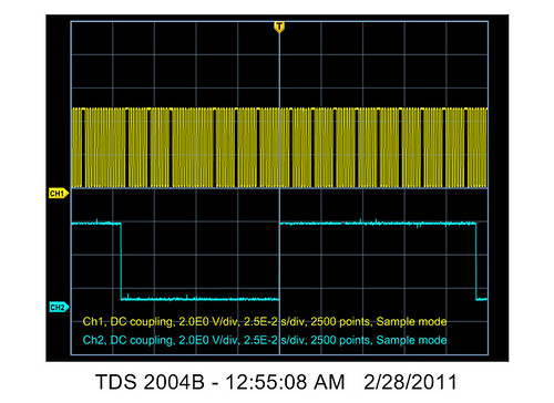
I have a AVR C implementation which I'm still extending to multiple channels. But this really works,and the difference in flicker is quite dramatic. Here's a scope shot of the same duty cycle with fast modulation (top, channel 1) and classic (bottom, channel 2) 256-level PWM. (The duty cycle is really the same, just the width of the scope trace makes it look greater on Channel 1):
I don't know of a good way to quantitatively measure it but I can reduce the PWM frequency to the point where you can see the individual cycles of classic PWM, but the fast modulation looks smooth except at the very lowest PWM values.
So I think this is a pretty major improvement in PWM routines. At the cost of a few cycles in the timer interrupt, you get much less flicker for a given PWM frequency. So you can reduce the timer rate which pretty much gets you back the cycles you lost by the additional computation. It could be argued that this is less efficient — it is doing a lot more switching, so those losses will increase — but once againyou can run it at a much lower frequency for similar perceptible flicker. So for battery operated devices this might also be preferable.