Sunday, May 29, 2016
Red-Green Laser Show Teardown
I wanted some moderately powerful lasers for a new project I am prototyping. While laser modules are available from various vendors like DealExtreme and AliExpress, various regulations and import restrictions can make this tedious.
NOTE: laser safety regulations are there for a reason! This is all fun and games until someone literally loses an eye. Don't be the dope who does damage like this!
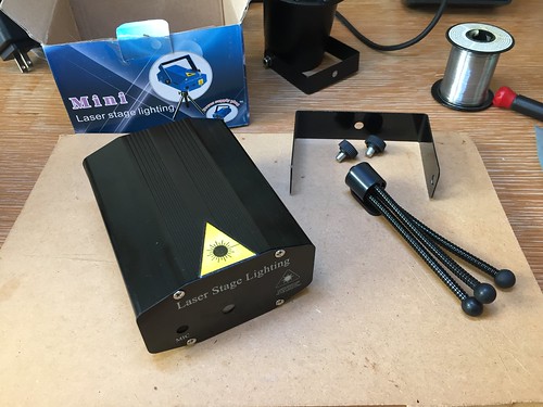
So it looks like an inexpensive way to get modestly powerful laser modules is to extract them from cheap stage lighting effects. Here's a $15 one I found on Amazon. Not only does it have red and green lasers, but it even comes with a tiny tripod! The exact model I purchased seems to have disappeared from Amazon but this one looks identical.
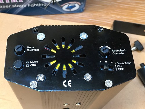
I'm sure you've seen one of these in the wild: the lasers shine through a diffraction grating that splits the beam in to a diffraction pattern: usually a square grid of dots but sometimes pictures. Here's the back panel showing the controls. It can respond to audio, flash automatically, and there's a motor that spins the diffraction grating with a speed control.
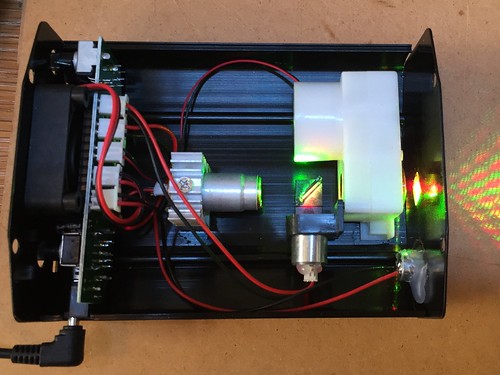
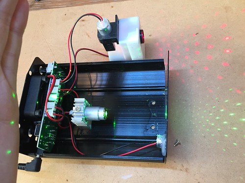
So lets' take it apart! There's a PCB with the controls in the back, green and red laser modules, and a dichroic mirror to combine them on the same axis. The green laser is bigger than the red, fairly obviously it's a common diode-pumped frequency-doubled 532 nM unit. The white unit is a small DC gearhead motor that spins a small tube around the combined beams with a diffraction grating on the exit. There's another diffraction grating just glued to the exit window at the front.
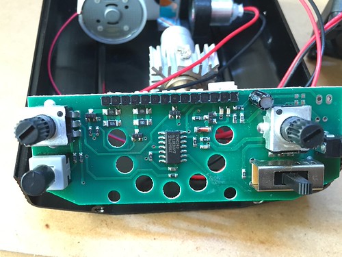
Let's take a look at that PCB. There is only one IC: a 74HC04 CMOS inverter, pretty much the most basic integrated circuit you can find! This is doing multiple duty: as a speed controller for the motor, and an oscillator for the "stroboflash" function, and a comparator for the audio input. The lasers are turned on and off via small SOT23 transistors controlled by the inverter outputs.
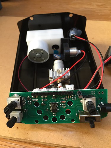
I didn't figure out the oscillator circuits in any detail, but inverter ring oscillators with RC speed control are a pretty well known trick. What I was most interested in was the laser drivers. These need a relatively constant current. More sophisticated laser drivers have a constant-current circuit, but here the current is supplied by simple current limiting resistors (the two sets of larger SMD resistors in parallel). I'm guessing they are counting on a well-regulated supply and the fan to stop any thermal runaway. Note that pretty much every laser diode I've seen has a third terminal -- this is the cathode of a phototransistor which is typically used in a feedback circuit to precisely control laser output. Since any kind of precision here would clearly cost too much, it's left unattached.
So there you have it. I've exploded the various parts so you can see the red and green lasers separately. Notice the backscatter of green laser light from the diffraction grating: might be time to invest in some laser safety goggles.
So a lot of useful parts and a case, and even a tripod: not bad for fifteen bucks! On deck for next week: a more sophistcated red-blue unit.